Georeferencing with IDRISI Taiga
Open a raster file in IDRISI Taiga
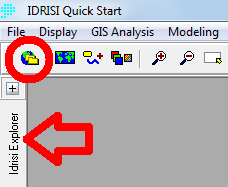
Start with change the project environment to the catalog with the files you will use. If the Idrisi Explorer is compressed to the left (see the red arrow in the figure below) click at the +. If the Idrisi Explorer is hidden, click at the symbol marked with the red circle in the figure below.
Go to Projects and rigth click anywere in that box. Choose New Project and browse to the catalog with the files you want to use.
Import the raster file you want to use with help of the commando ((choose another format if the image is not TIFF):
:File » Import » Desktop Publishing Formats » GEOTIFF/TIFF
GeoTIFF/Tiff to Idrisi should be selected. Select the image in GeoTIFF filename. The image will then be transformed to an Image file with the suffix .RST. Write the new name and check what catalog it will be in by clicking the icon to the right. Then select OK.
Metadata
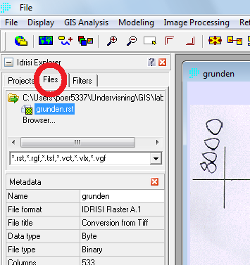
One way to learn more about the file before start the acctual georeferencing is to check the metadata. Go to Files in Idrisi Explorer ((see the red circle in the figure below).
Select your file in Idrisi Explorer, the metadata for the file then appear below. The metadata includes for example the number of columns and rows and also the coordinates. Note that you can also see the coordinates in the lower part of the window when you move the cursor over the image.
Georeferencing
We need to change the geographical location of the image, i.e. create real coordinates. Select:
:Reformat » RESAMPLE
Select your image as the Input image. In the field Output image choose a new name.
We will now enter the new coordinates. We have no specific map to compare with i.e. a output reference but we have an input reference. Select the image you want to give coordinates as input reference. The map will open in a new window. Zoom in on any of the corners of the image with the composer or with icons on the menu ((Zoom window).
Under the text Digitize GCP ((Ground control points) you can find the button Input. Press input to add a control point. A circle is now created in the middle of the image; move it with the mouse to one of the corners. In the Resample window the new coordinates are visible. Write the new coordinates.
When one point is ready go to the next with Input ((under digitize GCP). Make all four points. Go on if the RMS values are reasonable ((i.e. low, not over 5). They indicate how much the image is bent/distorted. The points can be saved for future use if you want, they will get the suffix * .cor and cannot be confused with other files.
An alternative, if you know the extent of the image “old” and “new” coordinates. The “old” coordinates in the image can be seen in meta data for the image.
We need to set the resolution and the limits of X and Y by pressing the “Output reference parameters” button. Write the minimum and maximum X and Y values found in the image. For the number of columns and rows, choose something similar to the original image ((found in metadata) but if the X and Y values constitute a perfect square, this must also be represented in the columns and rows. For example, minimum X: 3000 and max x: 5000 and minimum y: 6000 and max y: 8000 makes a 2000×2000 square which means that the number of columns and rows must be the same number; for example 540 columns and 540 rows.
In reference system select ”plane”.
Press OK and a new raster image is created.
Change the palette
Observe that the palette that was created in the import is not automatically incorporated in the image. You have to select it manually from the:
Composer window > Layout Properties > Palette File
Choose the one with the name of the original image.


